Direct Current Circuits
Resistivity
Resistance depends on three things inside a component:
- Length: The longer the component, the higher the resistance.
- Area. The greater the area, the easier it is for current to flow and the lower the resistance.
- Resistivity ($\rho$), which is a constant dependingd on the material.
What is resistivity?
Resistivity is defined as the resistance of a 1m length with a $1m^{2}$ cross sectional area. It is measured in ohm-metres ($\Omega m$).
Resistivity can be calculated by the following equation:
$$ \rho = \frac {RA}{L} $$
Where $\rho$ is resistivity, $R$ is resistance, $A$ is cross-sectional area and $L$ is the length.
Worked Example
The heating element in a toaster has a radius of 0.2mm, a length of 0.8m and a resistivity of $1.10 \times 10^{-6}$.
$$ \rho = \frac {RA}{L} \\
\eqalign{
1.10 \times 10^{-6} &= \frac {R \times (\pi(0.2 \times 10^{-3})^2)}{0.8} \\
1.10 \times 10^{-6} \frac{0.8}{1.26 \times 10^{-7}} &= R \\
R &= 7\Omega
}
$$
Direct Current Circuit Rules
Cells in Series and Parallel
When cells are positioned in series, the total emf is equal to the sum of all the potential differences.
$$ V_{Total} = V_{1} + V_{2} + V_{3} $$
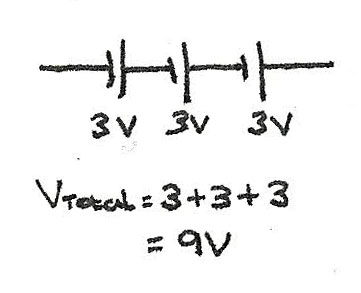
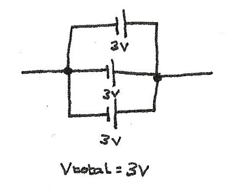
When cells are in parallel, the total potential difference supplied is equal to the pd of one of the cells.
$$ V_{Total} = V_{1} = V_{2} = V_{3} $$
Kirchoff's Laws
Direct current circuits follow Kirchoff's Laws which explain the current and emf behaviour.
Kirchoff's First Law
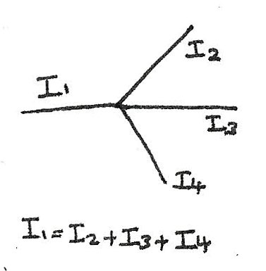
This states that the current entering a junction is equal to the current leaving it. In a circuit, the charge isn't used up or lost meaning whatever flows into a junction will leave it. In a series circuit, this causes the current to be equal everywhere in the circuit.
In a parallel circuit, the current depends on the resistance of each loop. Regardless of how the current is divided, the current entering the junction will always equal the current leaving it.
Kirchoff's Second Law
Kirchoff's Second Law states that the total emf of a series circuit is equal to the sum of the potential differences across all the component.
In series circuits the total pd is divided between all of the components.

In parallel circuits, the voltage across each loop is equal to the emf of the source.

Resistance Laws
These laws can be used to determine the resistance of components in circuit.
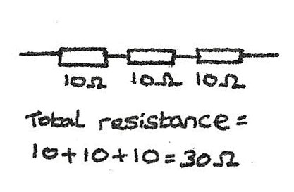
For circuits in series, the total resistance equals the sum of all the component resistances:
$$ R_{\text{Total}} = R_{1} + R_{2} + R_{3} $$
For circuits in parallel, the total resistance can be found using the following equation:
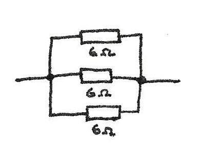
$$ \frac {1}{R_{Total}} = \frac{1}{R_{1}} + \frac{1}{R_{2}} + \frac{1}{R_{3}} \\
\frac {1}{R_{Total}} = \frac{1}{6} + \frac{1}{6} + \frac{1}{6} \\
\frac {1}{R_{Total}} = \frac {3}{6} \\
R_{Total} = 2\Omega $$
EMF and Internal Resistance
Resistance is caused by electrons colliding with atoms of the material and losing energy. In batteries, chemical energy is used to make electrons move. As they move, they collide with the battery, creating an internal resistance.
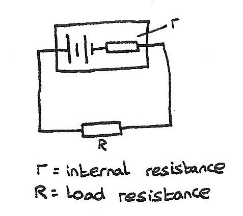
- The energy supplied per unit charge by the battery is called the emf ($\epsilon$).
- The amount of energy transferred when one coulomb of charge flows through the load resistance ($R$) is called the terminal pd ($V$).
With no internal resistance the emf would equal the terminal pd, though as there is an internal resistance energy is lost. This energy are the lost volts. The following equation can be used to calculate emf:
$$ \epsilon = IR + Ir $$
Uses of Internal Resistance
In order to deliver a high current, the source must have a low internal resistance. High voltage supplies are designed with a high internal resistance so that if a short circuit occurs, only a small current flows which is safer.
Potential Divider
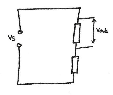
A potential divider is a circuit with a voltage source and some components in series. The potential of the supply is divided between the components so if a $2\Omega$ and a $3\Omega$ resistor are in series, the $2\Omega$ gets 2/5 of the voltage and the $3\Omega$ gets 3/5 of the voltage. The equation for a potential divider is:
$$ V_{out} = \frac {R_{1}}{R_{1} + R_{2}}V_{s} $$
LDR and Thermistors
LDRs and thermistors are often used in conjunction with a transistor in a potential divider circuit.
- The resistance of an LDR increases as the light level decreases.
- The resistance of a thermistor decreases as the temperature increases.
Potentiometers use the potential divider principle as a slider which moves the relative sizes of $R_{1}$ and $R_{2}$, changing the voltage across a component.

Alternating Current
An alternating current is a current that changes with time. In an alternating circuit, the voltage rises to a peak before decreasing to a trough, forming a sinusoidal pattern. To measure the voltage over time, an oscilloscope is used.
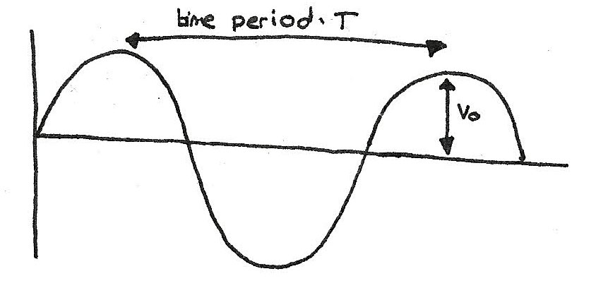
- The trace is produced by an electron beam moving across a screen.
- The time base controls how often the voltage is measured and plotted.
- The Y-gain is the voltage intervals shown on the screen.
By measuring the distance between successive peaks, the time period can be determined, which can be used to calculate the frequency.
$$ f = \frac {1}{T} $$
Root Mean Square
An alternating current with a peak voltage of 2V will actually be below 2V most of the time. This means the power output compared to a direct current supply will be much less. In order to compare the voltages, the root mean square average can be calculated:
$$ V_{rms} = \frac {V_{0}}{\sqrt{2}} \\
I_{rms} = \frac {I_{0}}{\sqrt{2}} $$