Electromagnetic Induction
Electromagnetic induction occurs when a conductor cuts across the field lines of a magnetic field, inducing an emf in the wire. In a complete circuit this induces a current which can be used for:
- Power stations. In most power stations, turbines rotate coils between a magnet which induces a current.
- Cycle dynamo. When a magnet in a dynamo spins, a current is induced, lighting a lamp. The work done by the cyclist in spinning the magnet is equal to the energy transferred to the lamp, assuming no energy is lost to the surroundings through friction or resistance.
Generator
With the motor effect, a current is applied which induces a force on the coil, making it spin. With a generator, a force is applied so the wire and magnet move relative to each other which induces a current in the wire:
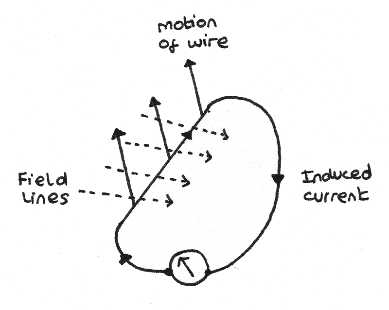
- As the wire is pulled upwards, there is relative motion between the magnet and the wire so an emf is induced. As the wire forms a complete circuit, a current is induced in a clockwise direction. When the motion of the wire stops, the induced current also falls to zero.
- If the motion of the wire is reversed, the direction of the current in the wire also reverses. In the above example, the current would flow anticlockwise around the circuit.
- The maximum emf is induced if the wire moves perpendicular to the magnetic field lines. If the wire is moved parallel to the field lines, no current flows.
Fleming's Right Hand Rule
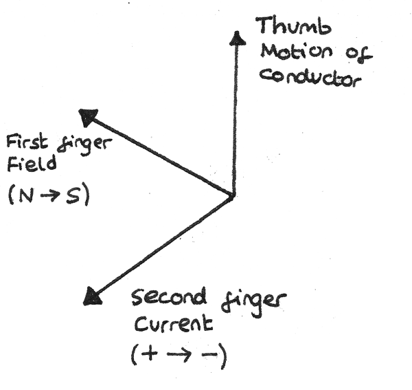
Fleming's right hand rule shows how the applied force, field lines and induced current all act perpendicular to each other.
Faraday's Law of Electromagnetic Induction
The diagram below shows a conductor of length $l$ which is part of a complete circuit cutting through the lines of a magnetic field of flux density $B$. The crosses indicate the magnetic field is acting into the plane of the diagram.
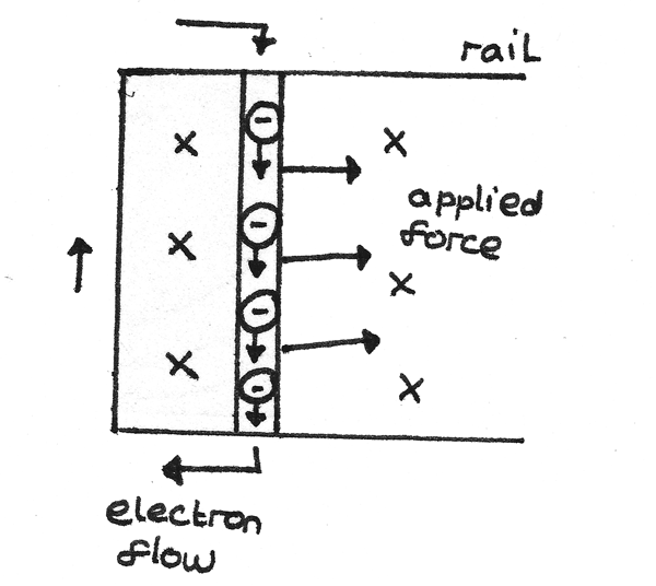
In moving the conductor through the magnetic field, an emf $\epsilon$ is induced and an induced current $I$ flows around the circuit. When using Fleming’s Right Hand rule to determine the direction of the current, it is important to understand that the direction of electron flow is opposite to the direction of flow of conventional current.
In passing through the field, the conductor experiences a force of $F = BIl$. To keep the conductor moving at a constant speed, an equal and opposite force must be applied to the conductor. If the conductor moves a distance $\Delta s$ in time $\Delta t$ then:
- The work done $W$ by the applied force is $W = F\Delta s = BIl\Delta s $.
- The charge transfer along the conductor is $Q = I\Delta t$.
The induced emf can then be calculated:
$$ \epsilon = \frac{W}{Q} = \frac{BIl\Delta s}{I\Delta t} = \frac{Bl\Delta s}{\Delta t} $$
As the area that the conductor passes through is equal to $l\Delta s$:
$$ \epsilon = \frac{BA}{\Delta t} $$
Alternatively, as $ \frac{\Delta s}{\Delta t} $ is equal to the velocity:
$$ \epsilon = Blv $$
This equation shows that in order to increase the induced emf, a stronger magnet or larger conductor could be used. The velocity of the conductor could also be increased.
Magnetic Flux
The magnetic flux is the product of the magnetic flux density, $B$, and the perpendicular area, $A$, the field lines penetrate.
$$ \phi = BA $$
The unit of magnetic flux is the weber ($Wb$) which is equal to $1~Tm^{2}$.
Magnetic Flux Linkage
Upon moving a coil through a magnetic field, the induced emf depends on the magnetic flux $\phi$ and the number of turns in the coil. The product of these is called the magnetic flux linkage:
$$ N\phi = BAN $$
Where $N\phi$ is the magnetic flux linkage ($Wb~\text{turns}$), $B$ is the magnetic flux density ($T$), $N$ is the number of turns on the coil and $A$ is the perpendicular area ($m^{2}$).
In the case that the field lines are not acting perpendicular to the plane of the coil such as in the diagram below:
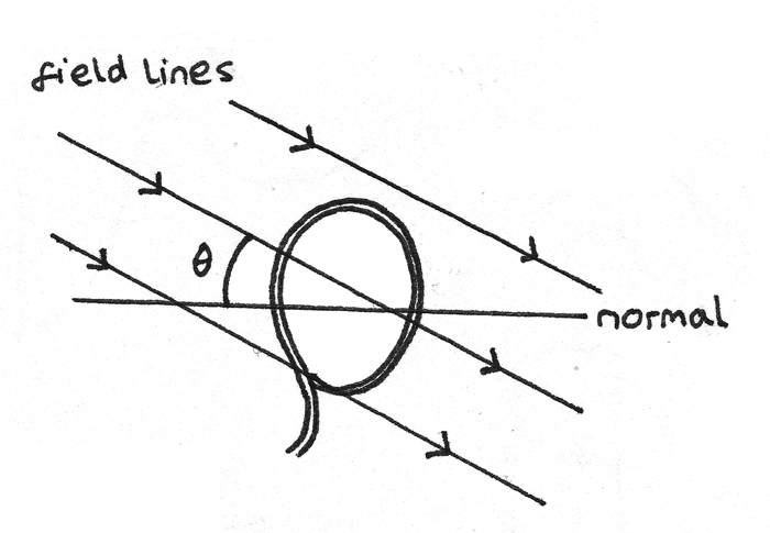
Then the magnetic flux and magnetic flux linkage are equal to:
$$ \phi = BA\cos \theta \\
N\phi = BAN\cos \theta $$
Where $\theta$ is the angle between the field lines and the normal to the plane of the coil.
Faraday’s Law
Faraday’s Law states that the induced emf in a circuit is equal to the rate of change of flux linkage:
$$ \epsilon = -N\frac{\Delta \phi}{\Delta t} $$
The minus sign represents the direction of the induced emf.
Lenz’s Law
Lenz’s law states that the direction of the induced current is always such as to oppose the change that caused the current.
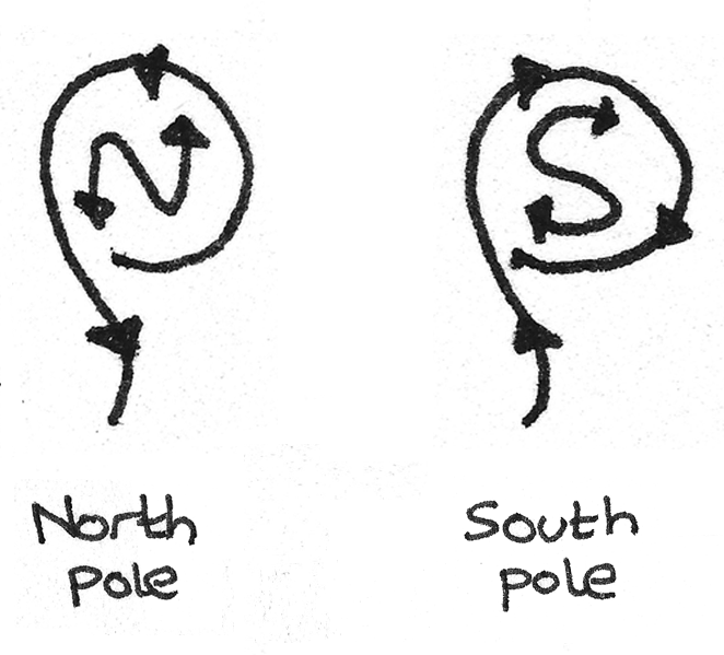
In a solenoid, the current passes anticlockwise around the north pole and clockwise around the south pole if each end is viewed from outside the solenoid in turn.
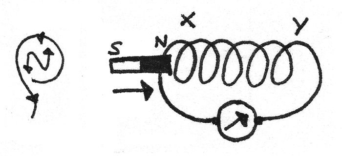
When the magnet is pushed into a coil, by Lenz’s law an induced current flows around the coil in a direction such to induce a force in the opposite direction to the magnet. In the example below, to induce the repulsive force the $X$ end must become a north pole, therefore the current must flow anticlockwise around the circuit.
When a magnet is pulled out of a coil, the induced force must reverse in order to try to pull the magnet back into the coil. To oppose the change the $X$ end must become a south pole. This means the current must flow clockwise around the circuit.
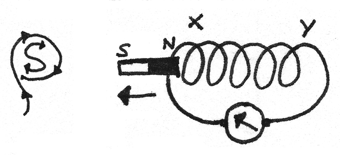
This opposition of the applied force is due to the conservation of energy principle. The energy used to pull a conductor through a magnetic field against the resistive force of the induced magnetic field is what produces the induced current.
AC Generators
AC generators produce an alternating current through the rotation of a coil in a uniform magnetic field. Brushes and slip rings connect a rotating shaft to a fixed complete circuit. At an instant when the angle $\theta$ is the angle between the coil and the normal to the field lines:
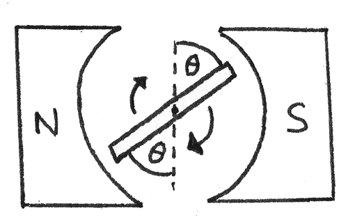
The flux linkage through the coil is:
$$ N\phi = BAN\cos \theta $$
Where $N\phi$ is the magnetic flux linkage ($Wb~\text{turns}$), $B$ is the magnetic flux density ($T$), $N$ is the number of turns in the coil and $A$ is the perpendicular area ($m^{2}$).
The orientation of the coil over a full cycle of time $T$ is shown below.

As the coil rotates, the value of $\theta$ changes so the flux linkage varies between $+BAN$ and $-BAN$. As $\theta = \omega t$, the flux linkage at time $t$ is:
$$ N\phi = BAN\cos \omega t $$
Where $\omega$ is the angular velocity of the rotating coil. The graph below shows the flux linkage over time.
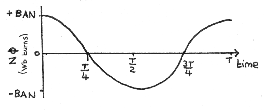
As the induced emf is equal to the rate of change of flux linkage over time, the gradient of the above graph is equal to the induced emf.
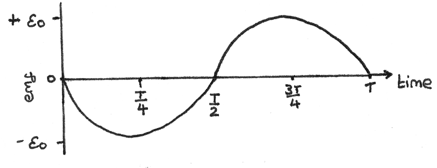
The induced emf at time $t$ can be calculated using
$$\epsilon = BAN\omega \sin \omega t $$
Where $\omega$ is the angular velocity of the rotating coil, $B$ is the magnetic flux density ($T$), $N$ is the number of turns in the coil and $A$ is the perpendicular area ($m^{2}$).
The peak emf occurs when $\sin \omega t = 1$, therefore:
$$\epsilon_{0} = BAN\omega$$
Where the peak emf $\epsilon_{0}$ is known, for a coil spinning at a frequency $f$ the induced emf is:
$$ \eqalign{ \epsilon &= \epsilon_{0}\sin \theta \\
\epsilon &= \epsilon_{0}\sin 2\pi ft } $$
This equation shows that the induced emf is at a maximum when the coil is in line with the field lines. This is because for a rotating coil, the rate of change of flux linkage is greatest when the flux linkage is zero.
Back Emf
When a motor spins in a magnetic field, it also acts as a generator as the flux linkage through the coil is changing. This induces an emf, $\epsilon$ which opposes the applied voltage. This emf is known as back emf. As the back emf opposes the applied voltage, $IR = V - \epsilon$. The induced back emf is proportional to the speed of the rotating coil therefore:
- At low speed, the current is high because the induced emf is low.
- At high speed, the current is low because the induced emf is high.
Transformer
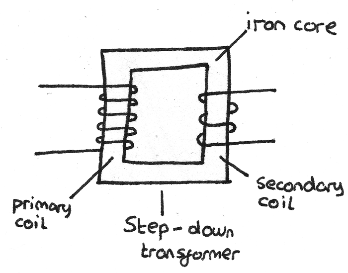
A transformer is a device that converts the voltage of an alternating current. It consists of a primary coil and a secondary coil wrapped around a soft iron core. When an alternating current is applied to the primary coil, a magnetic field is induced. This field passes through to the secondary coil, where an alternating emf is induced with the same frequency.
By Faraday's Law, the emf induced by the primary coil is:
$$ V_{p} = N_{p}\frac{\Delta \Phi}{\Delta t} $$
Where $V_{p}$ is the applied alternating pd, $N_{p}$ is the number of coils on the primary coil and $\frac{\Delta \Phi}{\Delta t}$ is the rate of change of magnetic flux.
In an ideal transfomer, all the magnetic flux produced by the primary coil passes through to the secondary coil so the pd across the secondary coil is:
$$ V_{s} = N_{s}\frac{\Delta \Phi}{\Delta t} $$
As the coils share the same magnetic field, the rate of change of flux will be equal, so the two equations can be combined to form the transformer rule:
$$ \frac{V_{s}}{V_{p}} = \frac{N_{s}}{N_{p}} $$
- A step up transformer has more coils on the secondary coil than the primary coil so $N_{s} > N_{p}$. This causes the voltage to be stepped up so $V_{s} > V_{p}$.
- A step down transformer has fewer coils on the secondary coil than the primary coil so $N_{s} < N_{p}$. This causes the voltage to be stepped down so $V_{s} < V_{p}$.
Efficiency
Transformers tend to have an efficiency close to 100% due to:
- A laminated iron core consisting of thin layers of iron separated by insulation. This reduces the induction of eddy currents which waste magnetic flux and heat.
- A soft iron core, which can be readily magnetised and demagnetised. This reduces the energy wasted in the magnetisation and demagnetisation of the core.
- Thick copper windings with a low resistance to reduce the wasted power output through heat due to the current.
In an ideal transformer, the power supplied by the primary coil is equal to the power output by the secondary coil therefore:
$$ \eqalign{ V_{p}I_{p} &= V_{s}I_{s} \\
\frac{V_{p}}{V_{s}} &= \frac{I_{s}}{I_{p}}} $$
This equation shows that for a:
- Step up transformer, where the voltage is increased as $V_{s} > V_{p}$, the current will decrease so $I_{s} < I_{p}$.
- Step down transformer, where the voltage is decreased as $V_{s} < V_{p}$ the current will increase so $I_{s} > I_{p}$.
The efficiency of a transformer is the ratio between the power output to the power input:
$$ \text{efficiency} = \frac{V_{s}I_{s}}{V_{p}I_{p}} $$
National Grid
Transformers are used for the transmission of electricity with a high efficiency over long distances. In a wire, the power lost due to the resistance is:
$$ P = I^{2}R $$
In order to minimise the power loss, the current should be kept to a minimum. At a power station, the voltage is stepped up to around $400kV$ for transmission, which reduces the current. For domestic use, a step down transformer reduces the voltage to around $230V$.