Magnetic Fields
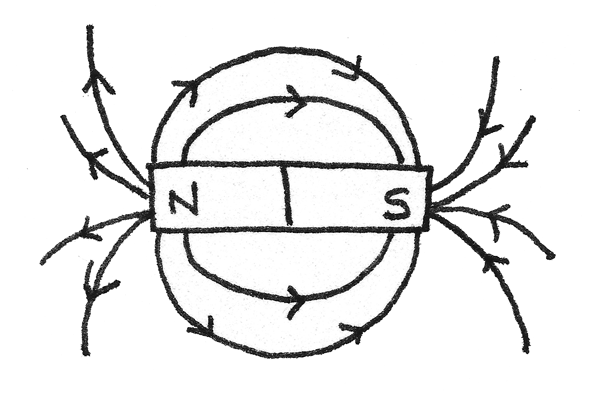
A magnetic field is a region surrounding a permanent magnet or current-carrying wire where a magnetic force is exerted on any other magnet, current-carrying wire or moving charged particle inside the field. The image below shows the magnetic field lines around a bar magnet:

Magnetic field lines indicate the path a free north pole would move in a field; which is always from north to south. As shown in the diagram, the lines are most dense at the poles of the magnet, where the magnetic field is at its strongest.
Magnetic Force
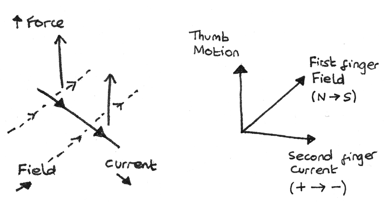
A current flowing through a wire induces a magnetic field around the wire. When a current-carrying wire or magnet is placed inside an external magnetic field, the two magnetic fields interact. This causes a force to act on the object in a perpendicular direction to the lines of force of the external field. The diagram below shows how the directions of the force, field lines and current are related.

If the current acts parallel to the field lines then no force acts. The directions of the motion, field lines and current can be represented using Fleming's left hand rule. This rule states that when the fingers are arranged perpendicular to each other, the thumb represents the line of action of the force, the first finger represents the field lines and the second finger represents the current.
When the magnetic field lines and the conductor are perpendicular, the magnitude of the force is proportional to the magnetic flux density in teslas, ($T$), the current ($A$) and the length of the wire ($m$):
$$ F = BIl $$
In order to increase the force, the wire can be coiled into a solenoid, thus increasing the length. This produces a magnetic field shaped like a bar magnet.
Magnetic Flux Density
The magnetic flux density, $B$ is a vector quantity defined as the force per unit length per unit current on a current-carrying conductor, perpendicular to the magnetic field lines. It is also known as the magnetic field strength. Magnetic flux density is measured in teslas, $T$.
Motor Effect
The motor effect is used in electric motors in order to make a central armature continuously rotate. An electric motor consists of a coil which spins between the poles of a magnet. When a direct current flows through the coil, forces act on both edges of the coil in opposite directions. This causes a torque, resulting in a rotating motion.

A split ring commutator is used to change the direction of the current every half rotation. By changing the direction of current, it reverses the direction of the applied force, allowing the armature to continuously spin in one direction when the coils move between the poles of the magnet.
Force on a Moving Charge
A current is caused by the flow of electrons, which are charged particles. These charged particles experience a force from the magnetic field. As current is the charge passing a fixed point per unit time, $I = \frac{Q}{t} $ and the distance an electron travels is $l = vt$, a formula for the force experienced by each individual charged particle can be found:
$$ \eqalign{ F &= BIl \\
F &= Bvt\frac{Q}{t} \\
F &= BQv }$$
Where $B$ is the magnetic flux density, $Q$ is the charge on one charged particle and $v$ is the velocity of the particle. It is the cumulative force from these charged particles which results in the visible movement of the wire.
In a complete circuit it is important to note that the direction of flow of electrons is opposite to the direction of flow of conventional current.
Cyclotron
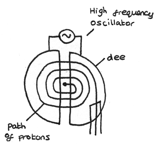
A cyclotron is a device used to accelerate charged particles to high velocities, often for use in radiation therapy or scientific research. A cyclotron consists of two semicircular electrodes called dees in a vacuum chamber.

A cyclotron makes use of a fixed magnetic field and an alternating electric field.
The magnetic field causes the particles to travel in a circular path around the dees. This is because when the field is applied into the plane of the diagram, the force applied on the charged particle acts perpendicular to the velocity of the charged particle. This results in the magnetic force acting as a centripetal force, causing circular motion. The centripetal force accelerates the particle only through changing the direction of motion not the speed.
A high frequency alternating voltage is applied between the dees. The charged particle is then accelerated across the space between the dees as they are attracted to the oppositely charged electrode. As the speed of the charged particle increases, the radius of its circular path increases.
As the magnetic force acts as the centripetal force, a formula for the radius of the circular path can be determined:
$$ \eqalign{ BQv &= \frac{mv^{2}}{r} \\ r &= \frac{mv}{BQ}} $$
This equation shows that increasing the mass or velocity of the charged particle increases the radius. Increasing the strength of the magnetic field decreases the radius.
By rearranging this equation in terms of $v$, it can be shown that the time taken for the particle to travel around a semi circular dee is independent of the velocity:
$$ \eqalign{ t &= \frac{\pi r}{v} \\ t &= \frac{m\pi}{BQ} }$$
As the voltage must be reversed each time the particle switches between the dees, the time period and frequency of the oscillator must be:
$$ T = \frac{2m\pi}{BQ} \\
f = \frac{1}{T} = \frac{BQ}{2m\pi} $$
Mass Spectrometer
A mass spectrometer is a device used to analyse the type of atoms present in a sample.

- First the atoms are ionised so that electric and magnetic fields can have an effect on them.
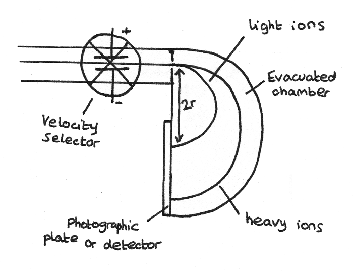
- Next the ions are accelerated through a velocity selector which ensures all the ions are travelling at the same speed. The velocity selector consists of a magnet and a pair of charged parallel plates. Each ion passing through the velocity selector is acted on by an electric force, $F_{\text{elec}}$ and a magnetic force, $F_{\text{mag}}$ in opposite directions. Ions at the selected velocity have the $F_{\text{elec}} = F_{\text{mag}}$ and therefore pass through undeflected.
- In a separate evacuated chamber, the ions are deflected by a magnetic field. The magnetic force acts as a centripetal force resulting in the ions travelling in a circular path with radius:
$$ r = \frac{mv}{BQ} $$ - As all the velocities of the ions are equal and the magnetic field strength, $B$, is constant, the charge to mass ratio of the ion can be determined by measuring the distance, $2r$ from the point of detection on the detector to the slit.